Instantiating a Computational Graph in Python
This page describes how to create a Computational Graph, instantiating Input, Output and Functional nodes and connecting them with edges. The created graph can be afterwards executed by the EventLoop. For this purpose, a set of Python decorators are provided; their use is described below.
The main decorator is @FunctionalNode, which takes a Python function and creates a Functional Node from it.
The rest of the decorators always decorate a @FunctionalNode. They allow to create Input and Output Nodes of the different available types and connect the decorated Functional Node to them.
All the decorators are defined in the nrp_core.event_loop Python module.
@FunctionalNode
Functional Nodes can be created from a Python function using the @FunctionalNode decorator. The Node will then execute this function every Event Loop cycle.
The code snippet below shows the creation of a simple Functional Node which just forward each of its two inputs to its two outputs.
@FunctionalNode(name="my_node", outputs=['output_1', 'output_2'], exec_policy=node_policies.functional_node.exec_policy.on_new_message)
def my_function(input_1, input_2):
    return [input_1, input_2]
The decorator has three arguments:
name: string used as the nodeidin the graph and must be therefore unique in the graphoutputs: a list of strings declaring the number and names of outputs of this node.policy(optional): the execution policy of the node. Its value must be of typenode_policies.functional_node.exec_policy, an enum with possible values:alwaysandon_new_message. Its default value ison_new_message.
Each of the declared outputs can be connected to other nodes using decorators. Each of the input arguments of the function can be connected to other nodes too.
The decorated Python function can return either None or a list with length equal to the number of declared outputs in the Functional Node decorator. Otherwise a runtime error is triggered.
Returning None can be used in cases when the function can’t produce valid outputs.
@FromFunctionalNode
This decorator allows to connect one Functional Node input port to another Functional Node output port. It, therefore, creates an edge in the Computational Graph between two Functional Nodes.
The code below will create a Functional Node with one input, input_1, and one output output_1, and connect input_1 to an output Port with id output_2 from a node with id my_node.
@FromFunctionalNode(keyword='input_1', address='/my_node/output_2')
@FunctionalNode(name="my_node_2", outputs=['output_1'])
def my_function_2(input_1):
    return [input_1]
The decorator has two arguments:
keyword: id of the input port in the decorated functional node which will be connected.address: address of the output port which will be connected.
The expected syntax for the output port address is /node_id/port_id. If a node with id node_id doesn’t exist or doesn’t have an output with id port_id, a runtime error will occur.
@FromEngine
This decorator creates an InputEngineNode and connects it to one of the decorated Functional Node inputs. It, therefore, creates a node and an edge in the Computational Graph.
The code below extends on a previous example by connecting input_1 in my_node to an output my_datapack of an InputEngineNode with id my_engine.
@FromEngine(keyword='input_1', address='/my_engine/my_datapack')
@FunctionalNode(name="my_node", outputs=['output_1', 'output_2'])
def my_function(input_1, input_2):
    return [input_1, input_2]
If my_engine doesn’t exist in the graph it is created. Then an Output Port my_datapack is registered with my_engine and datapack id my_datapack is added to the node requested datapacks. See here for more details.
The decorator has three arguments:
keyword: id of the input port in the decorated functional node which will be connected.address: address of the output port which will be connected.cache_policy(optional): the message cache policy of the node. Its value must be of typenode_policies.input_node.msg_cache, an enum with possible values:clearandkeep. Its default value iskeep.
@ToEngine
This decorator creates an OutputEngineNode and connects it to one of the decorated Functional Node outputs. It works in a very similar way to the previous one.
The code below extends the previous example by connecting output_1 in my_node to an OutputEngineNode with id my_engine.
@ToEngine(keyword="output_1", address="/my_engine")
@FromEngine(keyword='input_1', address='/my_engine/my_datapack')
@FunctionalNode(name="my_node", outputs=['output_1', 'output_2'])
def my_function(input_1, input_2):
    return [input_1, input_2]
The decorator has two arguments:
keyword: id of the output port in the decorated functional node which will be connected.address: address of the input port which will be connected.
It can be noted that from the example above, according to the descriptions given, two nodes with the same id, my_engine, would be created. Since node ids must be unique in the graph and in order to still allow using the same Engine name for both Input and Output Engine node ids, when an OutputEngineNode is created with a particular id, it internally adds the postscript "_output" to it. In the same way, InputEngineNodes add ‘“_input”’ to their ids. In this way, from the example above three nodes will be created with ids: my_engine_input, my_engine_output and my_node.
@RosSubscriber
This decorator creates an InputROSNode and connects it to one of the decorated Functional Node inputs. It creates, then, a node and an edge in the Computational Graph.
The code below extends on the previous example by connecting input_2 in my_node to an output port /my_topic of an InputROSNode with id /my_topic.
@RosSubscriber(keyword="input_2", address="/my_topic", type=nrp_core.data.nrp_ros.std_msgs.String)
@ToEngine(keyword="output_1", address="/my_engine/my_datapack")
@FromEngine(keyword='input_1', address='/my_engine/my_datapack')
@FunctionalNode(name="my_node", outputs=['output_1', 'output_2'])
def my_function(input_1, input_2):
    return [input_1, input_2]
The decorator has five arguments:
keyword: as in other decorators, specifies the name of the Functional Node input port that the decorator connects.address: tells the ROS topic to subscribe to.type: the ROS message type that is received through this ROS topic.cache_policy(optional): the message cache policy of the node. Its value must be of typenode_policies.input_node.msg_cache, an enum with possible values:clearandkeep. Its default value iskeep.publish_policy(optional): the message publish policy of the node. Its value must be of typenode_policies.input_node.msg_publish, an enum with possible values:lastandall. Its default value islast.
In this case, a new InputROSNode is created to subscribe to each different topic. From each @RosSubscriber decorator a node with id address is created, and an OuputPort with id also address is added to it.
The value used in the type argument of the decorator must be a class from nrp_core.data.nrp_ros Python module. These are the ROS message types supported in NRP-core. For more information about which are the message types supported by default see here. For information about how to compile NRP-core to support additional ROS message types see here.
@RosPublisher
This decorator creates an OutputROSNode and connects it to one of the decorated Functional Node outputs. It adds a node and an edge to the Computational Graph.
The code below extends on a previous example by connecting input_1 in my_node_2 to an input port /my_topic_2 of an OutputROSNode with id /my_topic_2.
@RosPublisher(keyword="output_1", address="/my_topic_2", type=nrp_core.data.nrp_ros.std_msgs.String)
@FromFunctionalNode(keyword='input_1', address='/my_node/output_2')
@FunctionalNode(name="my_node_2", outputs=['output_1'])
def my_function_2(input_1):
    return [input_1]
The decorator has the next arguments:
keyword: specifies the name of the Functional Node output port that the decorator connects.address: tells the ROS topic to publish to.type: the ROS message type the ROS topic this node publishes too.compute_period(optional): ComputePeriod of the node, 1 by default.publish_from_cache(optional): publishFromCache property of the node, false by default.
It is not possible to subscribe and publish to the same topic from a graph. Attempting to do this will result in having two nodes with the same id, which is not allowed.
@FromSpiNNaker
This decorator creates an InputSpiNNakerNode and connects it to one of the decorated Functional Node inputs. It, therefore, creates a node and an edge in the Computational Graph.
The code below connects input_1 in my_node to the spiking output of a Population pop_1 defined in SpiNNaker PyNN code. Note that the label of the Population is the import part, not the Python variable name. Also note that the Population must be activated for live output for this to be recieved by the function.
import pyNN.spiNNaker as sim
sim.setup(1.0)
my_pop_1 = sim.Population(5, sim.IF_curr_exp(), label="pop_1")
sim.external_devices.activate_live_output_for(my_pop_1, notify=False)

@FromSpiNNaker(keyword='input_1', address='pop_1')
@FunctionalNode(name="my_node", outputs=[])
def my_function(input_1):
    print(f"Spikes received from {input_1['label']} at time {input_1['time']}:"
          f" {input_1['neuron_ids']}")
    return []
The decorator has four arguments:
keyword: specifies the name of the Functional Node input port that the decorator connects.address: the SpiNNaker population to receive spikes or voltage from.cache_policy(optional): the message cache policy of the node. Its value must be of typenode_policies.input_node.msg_cache, an enum with possible values:clearandkeep. Its default value iskeep.publish_policy(optional): the message publish policy of the node. Its value must be of typenode_policies.input_node.msg_publish, an enum with possible values:lastandall. Its default value islast.
For a complete example using Spinnaker node decorators see examples/event_loop_examples/husky_braitenberg_spinnaker. In this experiment can be seen how to use @FromSpiNNaker decorator to access neuron voltages from the Computational Graph.
@ToSpiNNaker
This decorator creates an OutputSpiNNakerNode and connects it to one of the decorated Functional Node outputs. It, therefore, creates a node and an edge in the Computational Graph.
The code below connects output_1 in my_node to a SpikeInjector Population pop_1 defined in SpiNNaker PyNN code. Note that the label of the Population is the import part, not the Python variable name.
import pyNN.spiNNaker as sim
sim.setup(1.0)
my_pop_1 = sim.Population(5, sim.SpikeInjector(), label="pop_1")
sim.external_devices.activate_live_output_for(my_pop_1, notify=False)

@ToSpiNNaker(keyword='output_1', address='pop_1')
@FunctionalNode(name="my_node", outputs=[output_1])
def my_function():
    out = NlohmannJson()
    out['neuron_ids'] = list(range(5))
    return [out]
The decorator has two arguments:
keyword: specifies the name of the Functional Node output port that the decorator connects.address: the SpiNNaker population to send spikes to or update the rates of.compute_period(optional): ComputePeriod of the node, 1 by default.publish_from_cache(optional): publishFromCache property of the node, false by default.
In the aforementioned experiment located at examples/event_loop_examples/husky_braitenberg_spinnaker can be seen how to use @ToSpiNNaker decorator to control the rate of a SpikeSourcePoisson.
@MQTTSubscriber
This decorator creates an InputMQTTNode and connects it to one of the decorated Functional Node inputs. It creates, then, a node and an edge in the Computational Graph.
The code below subscribes to an MQTT topic ‘test_topic’ and connects incoming msgs to ‘my_function’ ‘mqtt_in’ argument. These messages are printed out inside of the function and a new message published to ‘test_topic’ from the function return value. In this way, in the created Computational Graph, the node ‘mqtt_str’ prints out its own published message in a loop.
@MQTTSubscriber(keyword='mqtt_in', address="test_topic", type=str)
@MQTTPublisher(keyword="mqtt_out", address="test_topic", type=str)
@FunctionalNode(name="mqtt_str", outputs=["mqtt_out"], exec_policy=node_policies.functional_node.exec_policy.always)
def my_function(mqtt_in):
    if mqtt_in is not None:
        print('Message from mqtt str: {}'.format(mqtt_in))

    return ["Hi there!"]
The decorator has five arguments:
keyword: as in other decorators, specifies the name of the Functional Node input port that the decorator connects.address: tells the MQTT topic to subscribe to.type: the data type incoming MQTT messages will be converted to (see here).cache_policy(optional): the message cache policy of the node. Its value must be of typenode_policies.input_node.msg_cache, an enum with possible values:clearandkeep. Its default value iskeep.publish_policy(optional): the message publish policy of the node. Its value must be of typenode_policies.input_node.msg_publish, an enum with possible values:lastandall. Its default value islast.
Below are listed the possible valid values for the type argument in the decorator:
‘str’: incoming messages payload is passed to the connected function as a string
‘nrp_core.data.nrp_json.NlohmannJson’: payload is passed as JSON objects
Any of the protobuf message types compiled with NRP-Core. These can be found under the Python module: ‘nrp_core.data.nrp_protobuf’.
‘nrp_core.data.nrp_json.JsonDataPack’
Any of the protobuf datapack types defined in ‘nrp_core.data.nrp_protobuf’
‘str’ is always safe to use, but in case of using any of the other types a runtime error will occur if incoming MQTT message can’t be converted to that type. See the experiment ‘examples/event_loop_examples/mqtt_simple’ for examples of mqtt decorators using each of the supported types.
@MQTTPublisher
This decorator creates an OutputMQTTNode and connects it to one of the decorated Functional Node outputs. It adds a node and an edge to the Computational Graph.
The code below replicates the one above but using ‘NlohmannJson’ data type.
from nrp_core.data.nrp_json import NlohmannJson

@MQTTSubscriber(keyword='mqtt_in', address="test_topic_json", type=NlohmannJson)
@MQTTPublisher(keyword="mqtt_out", address="test_topic_json", type=NlohmannJson)
@FunctionalNode(name="mqtt_json", outputs=["mqtt_out"], exec_policy=node_policies.functional_node.exec_policy.always)
def my_function(mqtt_in):
    if mqtt_in is not None:
        print('Message from mqtt json: {}'.format(mqtt_in))

    out = NlohmannJson()
    out['hi'] = 'there'

    return [out]
keyword: specifies the name of the Functional Node output port that the decorator connects.address: the MQTT topic to publish to.type: the data type that published MQTT messages will be converted from (see here).compute_period(optional): ComputePeriod of the node, 1 by default.publish_from_cache(optional): publishFromCache property of the node, false by default.
@Clock
This decorator creates an InputClockNode and connects it to one of the decorated Functional Node inputs. It adds a node and an edge to the Computational Graph.
The code below would create a Functional Node which reads the current system clock and prints it out.
@Clock('clock_in')
@FunctionalNode(name="clock_example", outputs=[], exec_policy=node_policies.functional_node.exec_policy.always)
def my_function(clock_in):
    print("current system time: {}".format(clock_in))
    return []
As explained in this section, depending on whether the Computational Graph is being managed by an EventLoop or an FTILoop, the InputClockNode will stream either the current value of the internal (real-time) clock of the EventLoop, wrt the time point in which the loop was started, or the current simulation time, in the case of using an FTILoop.
keyword: specifies the name of the Functional Node output port that the decorator connects.
@Iteration
This decorator creates an InputIterationNode and connects it to one of the decorated Functional Node inputs. It adds a node and an edge to the Computational Graph.
The code below would create a Functional Node which reads the current loop iteration number and prints it out.
@Iteration('iteration_in')
@FunctionalNode(name="iteration_example", outputs=[], exec_policy=node_policies.functional_node.exec_policy.always)
def my_function(iteration_in):
    print("current loop iteration number: {}".format(iteration_in))
    return []
Either if the Computational Graph is being managed by an EventLoop or an FTILoop, the InputIterationNode streams the number of times the loop has been run.
keyword: specifies the name of the Functional Node output port that the decorator connects.
Putting the Examples Together
To conclude the overview of the available Computational Graph decorators lets put together the different examples shown in the sections above:
@RosSubscriber(keyword="input_2", address="/my_topic", type=nrp_core.data.nrp_ros.std_msgs.String)
@ToEngine(keyword="output_1", address="/my_engine")
@FromEngine(keyword='input_1', address='/my_engine/my_datapack')
@FunctionalNode(name="my_node", outputs=['output_1', 'output_2'])
def my_function(input_1, input_2):
    return [input_1, input_2]

@RosPublisher(keyword="output_1", address="/my_topic_2", type=nrp_core.data.nrp_ros.std_msgs.String)
@FromFunctionalNode(keyword='input_1', address='/my_node/output_2')
@FunctionalNode(name="my_node_2", outputs=['output_1'])
def my_function_2(input_1):
    return [input_1]
This script, when loaded by the EventLoop, will create a graph with six nodes:
two input nodes:
my_engine_input,/my_topic.two output nodes:
my_engine_output,/my_topic_2two functional nodes:
my_node,my_node_2
Five edges will be added to the graph:
From
my_engine_inputtomy_nodeFrom
/my_topictomy_nodeFrom
my_nodetomy_node_2From
my_nodetomy_engine_outputFrom
my_node_2to/my_topic_2
When the graph is configured, the nodes in the graph are divided into four layers (see here for more details), each containing the following nodes:
my_engine_input,/my_topic.my_nodemy_node_2my_engine_output,/my_topic_2
Ports required to connect the different Nodes are also created. The resulting graph is depicted in the figure below:
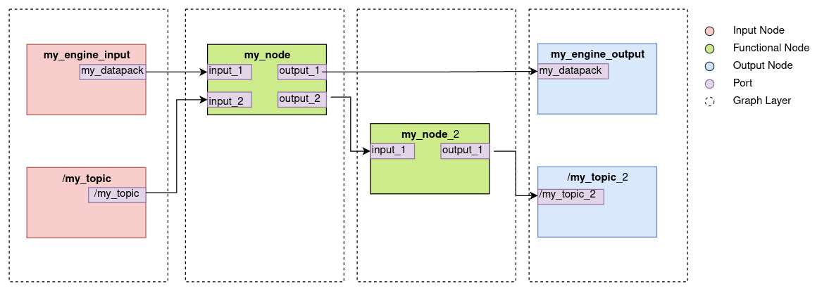
Each time the graph is executed (i.e. in every Event Loop cycle) the nodes in each of the layers are executed sequentially and in order. The next behavior is expected: If a new message has been published to the ROS topic /my_topic in the last event loop cycle, it will be sent to my_node, which will, in turn, forward it to my_node_2 and finally will be published to a /my_topic_2 ROS topic. my_engine_input node will publish the latest available datapack with id my_datapack from Engine my_engine to my_node input port input_1. The datapack will be sent back to the same Engine through the node my_engine_output.
As a final comment, the order in which the decorators are added in the Python script is arbitrary. Only the @FunctionalNode decorator must be placed directly above the Python function which will be executed.
For more examples on how the presented decorators are used to create Computational Graphs, take a look at the three example experiments provided in the examples/event_loop_examples folder.