Computational Graph
The Computational Graph provides event processing and publishing capabilities to the NRP-Core Event Loop. For this purpose three types of nodes, Input, Output and Functional, are available. These nodes can be connected with directed edges forming a graph structure. Through these connections, nodes can send data to each other. To handle the actual data transmission through these connections, nodes use Ports.
Input Nodes are used to subscribe to external events outside of the Event Loop and inject them into the graph. These events are always messages in any of the supported formats (e.g. ROS messages). Functional Nodes run an user-defined function which input arguments and return values can be both connected to other node Ports. In this way, they act as processing units in the Computational Graph. Output Nodes receive messages and publish them out of the Event Loop.
In this way, the Event Loop receives messages asynchronously through Input Nodes and process them synchronously through the sequential execution of the Computational Graph nodes. A new message arriving to an Input Node involves two aspects: an event, i.e. a new message has arrived, and the data, payload, contained in the message. Both are propagated to the nodes connected to the Input Node, usually Functional Nodes, triggering their execution.
Finally, the Computational Graph is purely functional, the execution of nodes does not produce side effects beyond the transmission of events and messages through their Ports. That is, neither the graph nor its nodes have any state variables which can be set or modified through the execution of the graph.
In the next sections different aspects of the Computational Graph elements, model and behavior are described. For convenience, each of these sections are linked below:
Graph Edges: Ports
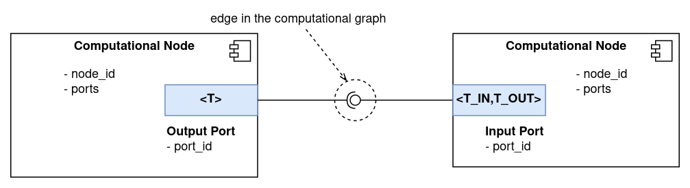
Edges in the Computational Graph represent connections between Computational Nodes through which data can be sent. To manage the actual data communication, Computational Nodes use Ports.
There are two types of Ports: Input and Output. As depicted in the figure below, both are templated, and can only be connected if their template parameters coincide. That is, in the figure, it would only be possible to connect the Output Port to the Input Port if T is equal to T_IN.
Output Ports are used by Nodes to send data to other Nodes. A publisher/subscriber pattern is used to manage data transfer operations. Output Ports have a publish(const T* msg) function which takes a pointer to an object of type T (the Port template parameter), and sends it to all subscribed Input Ports.
Input Ports have a subscribeTo(OutputPort<T_IN>* port) function which allows to subscribe to an Output Port of the right type. In their constructor, Input Ports take a callback function with signature "void (const T_OUT*)" which is called upon new message arrival.
In this way, Nodes can use ports to publish data and receive it through callback functions.
It can be noticed that Input Ports are templated with two types: T_IN and T_OUT. This opens the possibility of performing data conversion operations in Input Ports. See the section Data Conversion in Input Ports below for more details on how data conversion operations are implemented.
Additionally, it is possible to set the maximum number of Ouput Ports an Input Port can subscribe to. This feature is used by nodes in order to control the graph connectivity. For example, Functional Nodes allow to connect each of their inputs to one Port only.
Finally, each Port is uniquely identified in the graph by its address. This address is used to declare connections in the graph, see this page for more details. The address of each Port takes the form: /node_id/port_id. node_id is the id of the parent node of the Port, which is unique in the graph. port_id is the id of the Port, which is unique in the parent node.
Computational Nodes
Computational Nodes are the computation units in the graph. They are responsible for receiving and processing events and sending out other events in response.
All node implementations inherit from class ComputationalNode, which provides a basic interface used by the Computational Graph to configure and execute them. It has two virtual methods which every derived class must implement:
configure(): called in the graph configuring state. After the call returns the node is assumed to be ready for being executed.compute(): called when the node is executed in each loop cycle.
Computational Node Types
There are three types of nodes: Input, Functional and Output. Each of them is discussed in more detail below.
Input Nodes
Input Nodes receive events from out of the graph and propagate them to connected nodes. Input Nodes can only have Output Ports and thus can only be sources in graph edges.
The base implementation of InputNode has a registerOutput(const std::string& id) method which can be used to create ports in the node. For each registered port, a cache is created in the node. Derived classes must use this cache to place pointers to incoming messages. When compute() is called, InputNode publishes the content of each Port cache through the corresponding Port.
InputNode has a "bool updatePortData(const std::string& id)" virtual method which uses as a hook to ask derived classes to update the cache for a given port with id id. If the method returns true it means that new messages are available and ready to be published through this port. In this way, it is assumed that InputNode derived classes knows how to map incoming messages to ports in the node.
InputNode is templated with a parameter DATA which specifies the data type the node will publish. That is, all the ports in the node will be of type DATA.
Output Nodes
Output Nodes are used to send event messages out of the graph. They can only have Input Ports and therefore can only be targets in graph edges.
The base class OutputNode collects data coming through its ports. It has a virtual method "void sendSingleMsg(const std::string& id, const DATA* data)" which derived classes must implement and which is used to send out received messages.
OutputNode is templated with a parameter DATA which specifies the data type the node can handle. That is, all the input ports in the node will be of type <T_IN, DATA>. The class has a method getOrRegisterInput<T_IN>(const std::string& id) which allows to create ports in the node.
Finally, Output Nodes can be configured with two properties:
ComputePeriod: property specifying the number of graph cycles that passes between executions of this node. E.g. if it is set to 1, the node is executed every cycle, if it is set to 2, every other cycle, and so on.
publishFromCache: it is a boolean property. If it is set to ‘true’ the node will cache received messages in each cycle and in the next cycle, if no new messages were received, it will publish the same messages from the cache. If this property is set to ‘false’ the node will only publish fresh messages received in each cycle.
Using these two properties it is possible to make a node to publish messages at a fixed frequency, which might be desirable in robot control applications. Given the frequency at which the Computational Graph is run, it is possible to specify the publishing frequency by setting ‘ComputePeriod’ to the desired value. Then, by setting ‘publishFromCache’ to ‘true’ it is assured that the node will always publish even if no new messages were received.
Functional Nodes
This type of node is used to process incoming events and send other. It can have Input and Output Ports.
The node wraps a function which is called in its compute() method. Each of the function arguments can be connected to an Input Port, and each of its outputs to an Output Port. In this way, Functional Nodes can be used as computational units in the graph which process input data and publish its results through its Output Ports. By connecting these Output Ports to Output Nodes, the output of the function can be sent out of the graph.
Computational Node Implementations
This section describes the implementations available for Input, Functional and Output Nodes.
FunctionalNode is already the final implementation of a Functional Node. In contrast, there is an implementation of InputNode and OutputNode for each supported communication protocol. These are described below.
ROS Nodes
ROS nodes allow to interface a Computational Graph with the ROS middleware.
InputROSNode is an implementation of InputNode which subscribes to a ROS topic, which address is given in the node constructor, and publishes received messages through an Output Port. The class is templated with the ROS message type the node can subscribe to.
OutputROSNode implements an OutputNode which publishes incoming messages to a ROS topic, which address is specified in the node constructor. The class is templated with the ROS message type the node can publish.
Engine Nodes
This type of node allows to integrate the Computational Graph with the Engine interface used in the synchronous mode of NRP-core. This integration can be exploited in several ways which are described in this page.
InputEngineNode implements an InputNode specialization with type DataPackInterface. That is, it publishes messages of type DataPackInterface. It has two methods requestedDataPacks() and setDataPacks() which allows to update the node externally with the latest datapacks that the node subscribes to. requestedDataPacks() returns a set of DataPackIdentifier which corresponds to the datapacks the node requires.
OutputEngineNode implements an OuptutNode of type DataPackInterface*, and places all incoming messages in a cache which can be retrieved externally using the method getDataPacks().
SpiNNaker Nodes
SpiNNaker nodes enable interfacing with neural networks running on the SpiNNaker neuromorphic platform.
InputSpiNNakerNode is an implementation of an InputNode that receives either spike or voltage input data from SpiNNaker. Each node is associated with a Population in the neural network from which messages are to be received. The contents of the message received will be converted to a JSON formatted output. For spikes this will be an object with a “label”, representing the label of the Population; a “time” representing the simulation time step when the spikes were sent; and an array of neuron IDs which sent spikes at the time given. For voltages this will be an object with a “label, representing the label of the Population; and an array of objects each with an integer “neuron_id” and a float “voltage”. All neuron IDs in the received messages are local within the Population associated with the node.
OutputSpiNNakerNode is an implementation of an OutputNode that can send spikes to a SpikeInjector in a SpiNNaker neural network, or control the spike rate of a SpikeSourcePoisson within a network. Each node is again linked to a Population to which messages are to be sent. The messages sent to the node are expected as JSON formatted objects with a given structure. If the Population is a SpikeInjector, this will have an array of integers called “neuron_ids” which indicate the neuron IDs to send spikes to. If the Population is a SpikeSourcePoisson, this will have an array of objects called “rates”, each with a “neuron_id” and “rate”, indicating which source neuron to set the rate of, and what rate to set it to.
MQTT Nodes
MQTT nodes enable to connect the Computational Graph with MQTT topics.
InputMQTTNode implements an InputNode which subscribes to an MQTT topic and makes incoming messages available through an OutputPort. Incoming messages can be injected into the graph in the following data formats:
Strings containing the corresponding MQTT messages payload
JSON objects, which content is set from the MQTT message payload
Any of the protobuf message types precompiled with NRP-Core
Datapacks storing either a JSON object or a Protobuf message
The node is templated with the type of object incoming MQTT messages should be converted to.
OutputMQTTNode implements an OutputNode which publishes incoming messages to an MQTT topic. As in the case of InputMQTTNode, it can accept either strings, JSON objects or protobuf messages, which are set as payload in an MQTT message and published.
Time Nodes
This class encompasses nodes which can be used to input system time information into the Computational Graph. Currently there are two nodes available: InputClockNode and InputIterationNode. Both stream messages of type unsigned long.
InputClockNode streams a message through its only port, clock, containing the current “system time” in milliseconds. The meaning of system time is different depending on whether the Computational Graph is operated by an EventLoop or a FTILoop. See this page for more information about the possible ways of using a Computational Graph in NRP-Core. If an EventLoop is used to manage the runtime execution of the graph, InputClockNode sends the current value of the internal (real-time) clock of the EventLoop, wrt the instant in which the EventLoop started. If a FTILoop is used instead, InputClockNode sends the current simulation time, identically as the @SimulationTime decorator in TransceiverFunctions.
InputIterationNode streams a message through port iteration containing the current iteration number. In this case the content of the message is similar if the graph is operated either by an EventLoop of a FTILoop : the number of times the loop has been executed.
Execution Order of Nodes in the Graph
In each cycle of the Event Loop, all the nodes in the graph are executed in order. This order is directly defined by the edges between nodes present in the graph.
Since edges in the graph represent connections through which messages are sent, they impose precedence constraints in the execution order of nodes they connect. In each event loop cycle, the source node in an edge must always be executed before the target node. This basic rule ensures that all nodes are always executed with the latest data available.
Additionally, we want all the I/O operations in the graph to be executed at the beginning and at the end of the graph execution respectively. This can be translated as that all the Input nodes are executed first, then all Functional Nodes and finally all Output Nodes.
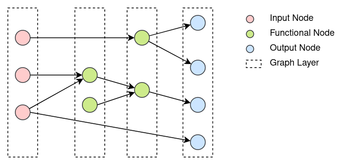
The former constraints indirectly allow to divide the graph in layers which must be executed sequentially and in order. These constraints can be translated in the next set of rules which completely define the graph layer structure:
All the input nodes and only input nodes are placed in the first layer
All the output nodes and only output nodes are placed in the last layer
In each layer nodes receive edges only from previous layers
All the nodes in each layer can be executed in parallel.
In the image below a Computational Graph and its division in layers is depicted:
Computational Graph Execution Modes
In the section above it was described the order in which nodes in the Computational Graph are executed each cycle, understanding that to execute a node means to call its ‘compute()’ function. Additionally, it is possible to filter out a subset of the graph nodes from being executed in each cycle, according to some pre-specified logic. This possibility can be accessed by changing the execution mode of the Computational Graph.
Currently, the execution modes available are: ‘ALL_NODES’ and ‘OUTPUT_DRIVEN’. In ‘ALL_NODES’ execution mode all nodes in the graph are executed in the order specified in the section above, i.e. there is no filtering. In ‘OUTPUT_DRIVEN’ mode only those Functional Nodes connected to Output Nodes which will be executed in the current cycle are executed. Output Nodes have ‘ComputePeriod’ property which can be used to define with which periodicity they are executed. See here for more details.
The behavior described above for the ‘OUTPUT_DRIVEN’ mode, is concreted in the list of steps listed below, which are executed at the beginning of each cycle:
The subset of the output nodes in the graph which should be executed in this cycle is collected
For each of these nodes, the subset of functional nodes connected to them, directly or indirectly, is collected
All of these subsets of nodes are marked to be executed in this cycle
Input nodes are always executed independently of to which functional or output nodes are connected, so new input to the graph is always processed
It must be noted that the different execution modes affect which nodes will be called to execute in each cycle, but each of these nodes will still execute according to their own policies.
Data Management in the Computational Graph
As it has been already explained, nodes exchange pointers with each other through ports. Also, Input Ports support automatic data conversion if its template parameters T_IN and T_OUT are different.
In order to avoid memory leaks and ensure that nodes always operate with pointers that are valid, a set of rules referring to data management in the Computational Graph are established. These rules, which are described below, should be preserved by all node implementations.
Data ownership:
Nodes own Ports.
Nodes own the pointers they publish through their Ports.
Input Ports own converted data.
Data pointers validity:
Nodes only publish data through their Output Ports from their
compute()functions.Nodes must ensure that pointers published through a given port are valid and the pointed data doesn’t change until a new pointer is published through the same port.
InputPort, FunctionalNode and OutputNode have been implemented to preserve these rules. But developers implementing new InputNode types must be careful of respecting rules 1.b, 2.a and 2.b in order to avoid memory leaks or unexpected runtime errors.
Data Conversion in Input Ports
As it was mentioned above, Input Ports take a callback function with the signature "void (const T_OUT*)" in their constructor. This function is called with new messages published to the port.
If the template parameters T_IN and T_OUT of an Input Port are different, then the received messages should be converted from T_IN to T_OUT in order to call the callback function with them. Conversion functions available to InputPort are placed in the file nrp_event_loop/nrp_event_loop/utils/data_conversion.h.
Currently, only conversions from and to boost::python::object are implemented.
Data Caching and Coherence
The Event Loop receives events asynchronously and processes them synchronously. Messages can arrive at any point in time to Input Nodes and they are processed sequentially by executing graph layers in order.
Input Nodes cache messages arrived to them and, when their compute() function is called, publish pointers to these cached messages through their Output Ports. The published pointers are received by Functional Nodes Input Ports and cached there to be used as input to their wrapped function. After a Functional Node is executed, it caches the output values of its wrapped function and publishes pointers to them through its Output Ports. Finally, Output Nodes also cache incoming messages to be sent through their sendSingleMsg() function when they are executed.
The process described above is repeated every event loop cycle. The implication of this design is that all the messages received by Input Nodes during the previous cycle are processed together and are therefore implicitly considered coherent. By imposing the rules 2.a and 2.b described in the section above, it is automatically enforced that all nodes in the graph operate with data that is coherent under the previous definition and which remains invariant during the graph computation.
Then there is another point to consider. The case in which an Input Node didn’t receive any message for one of its ports during the last event loop cycle. The figure below provides a graphical view of this possibility. Each green square represents the loop cycle in which the respective Input Node received the last message to be published in particular port.
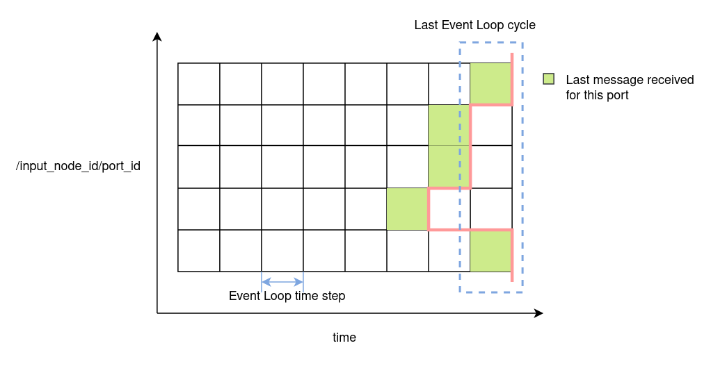
To handle this case two options are available:
keep the last cached message(s) and don’t publish any new pointer through its Port.
wipe the cache and publish a null pointer.
Option (1) will be desirable in cases where received messages contain an update of part of the state of a simulation or system. For example the value of a joint in a robot simulation or system. Option (2) will be desirable in cases where messages are meant to be processed just once. For example, a new object, which is detected by a computer vision component. Input Nodes can be configured to adopt one of these two options. Referring again to the figure above, if all nodes were configured with option (2), those nodes with a white square in the last cycle will send a nullptr. If option (1) was used, they will keep the last received message.
The implicit consequence of the behavior of Input Nodes described above is that functions used in Functional Nodes must always consider the case in which any of their inputs is a null pointer.
Node Execution Policies
There are several configuration options available which affect the execution behavior of Computational Nodes. These are described in this section.
Input Node
It was already mentioned in the section above that Input Nodes can be configured to keep their cached messages or wipe the cache and publish a nullptr in case they didn’t receive new messages in the last event loop cycle. This policy is referred to as MsgCachePolicy and its two possible values, KEEP_CACHE and CLEAR_CACHE, implement these two possible behaviors respectively. The default value is KEEP_CACHE.
There is another configurable execution policy available for Input Nodes, MsgPublishPolicy. It refers to how the node publishes cached messages. It can be set to LAST, in which case the node publishes only the last received message for each port, or ALL, in which case the node publishes all messages as a vector of pointers. The default value for this policy is LAST.
Functional Node
There is only one execution policy available for Functional Nodes, named plainly as ExecutionPolicy. It specifies the conditions under which the node should be executed. It can take two values: ALWAYS, in which case the node is executed in every event loop cycle; and ‘ON_NEW_INPUT’, in which case the node is only executed if at least one of its Input Ports received a new message in the current loop cycle. The default value is ON_NEW_INPUT.
Functional Nodes always keep the cached output from their wrapped functions. This means that if the node is not executed it won’t publish any new pointers, but those published in previous cycles will remain valid.
Output Node
Output Nodes have a single execution policy, with the name PublishFormatPolicy. It tells how the node publishes out cached messages. If set to SERIES, the node publishes each message individually and sequentially. If set to ‘BATCH’, it publishes all cached messages as a batch in a single message.
Output Nodes can be configured to publish only new messages arrived in the current cycle or to cache the last message and re-publish it in next cycles if no new message arrives. This option is described in more detail above in this /ref output_node “section”.
Computational Graph Lifecycle
The Computational Graph is always in one of the states described below. In each state, only some actions can be applied to the graph. The different states, transitions and possible actions are depicted in the figure below:
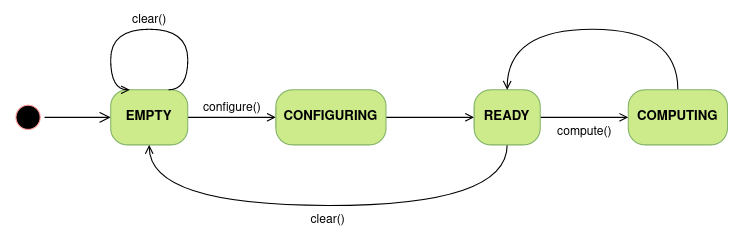
Computational Graph states:
Empty: the graph is created. This is the only state in which nodes and edges can be added to the graph.
Configuring: all nodes in the graph are configured and the graph layers are created.
Ready: the graph is ready for being executed.
Computing: the graph is being executed.