Basics of the NRP software architecture
The NRP is (very schematically) comprised of three complementary components:
the frontend, which includes the graphical user interfaces to control the NRP
the backend, where simulations are actually executed
data storage
The backend is of particular importance as this is where different simulators (e.g. Gazebo, NEST) are synchronized and provided with the means to exchange data through the Transfer Function framework. The latter pivotal role, as it provides users with a simple way to define how the different simulators communicate with each other, and in particular how the connection between brain and body is set up. Concretely, Transfer Functions are user-defined Python functions, the main purpose of which is to ensure that the output of a given simulator is converted into a format that can be consumed by another simulator. A nice feature of the Transfer Function framework is that any NRP simulation can be paused at any given time, and the Transfer Functions modified through the GUI. When unpausing the simulation, these modifications immediately take effect, enabling users to tailor the coupling between e.g. brain and body without the need to fully stop and re-launch experiments.
The main use of the NRP 3.2 is to provide simulated brain models with embodiment into a simulated, physically realistic world. To this end, the backend is comprised of a “brain simulation”, a world simulation, and an orchestration mechanism that makes sure these two simulations and the Transfer Function framework are properly synchronized (see Fig. 13). In NRP v3.2, this component is referred to as the Closed-Loop Engine (CLE) and runs in the same process as the brain simulator (NEST or NENGO). The “world simulation” engine is an integral part of the NRP and is a fork of the Gazebo Robotics simulation. It communicates with the CLE through ROS, thus providing a communications mechanism to e.g., control the simulations and display experiment-related data to the users through the GUI.
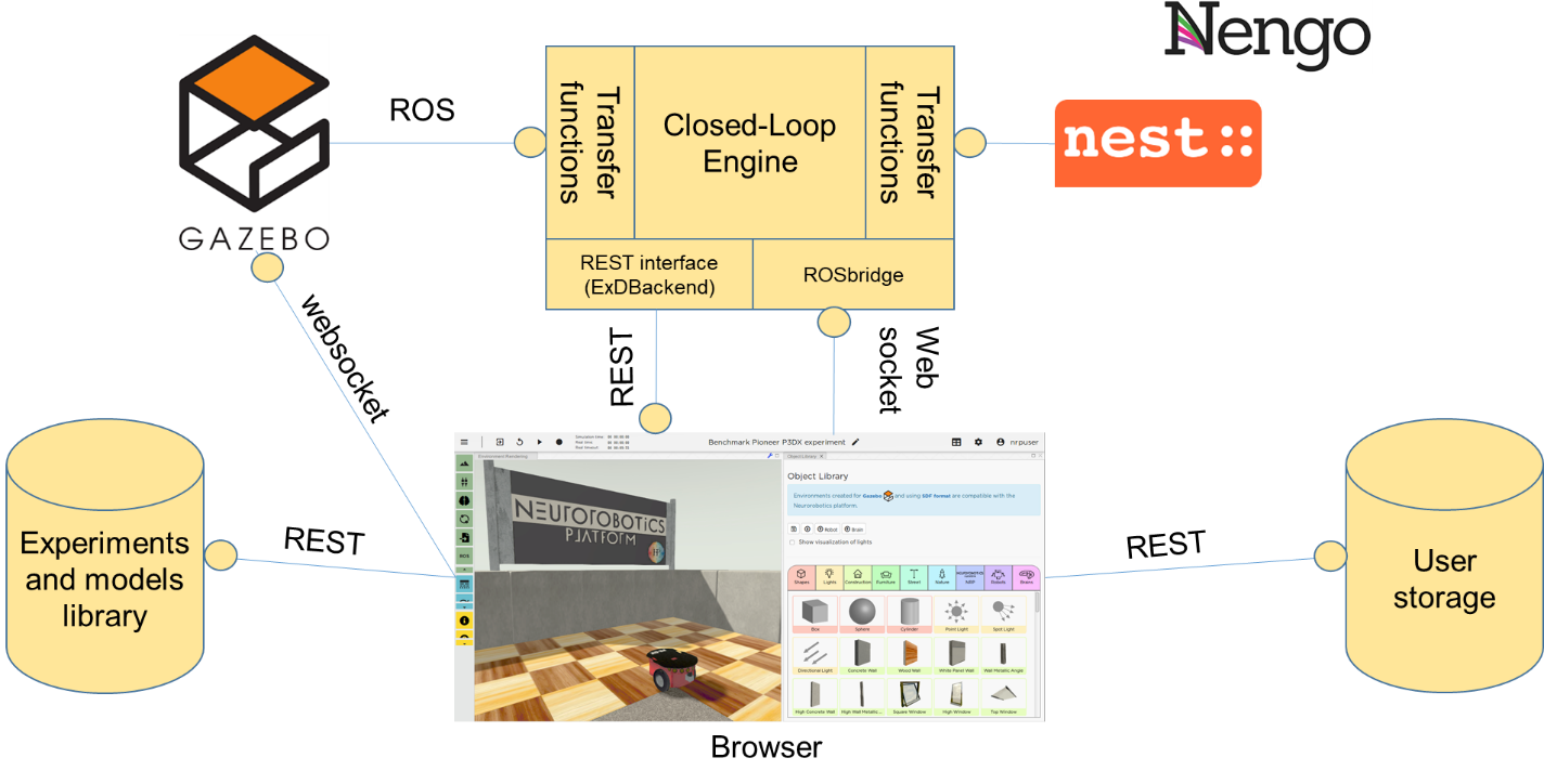
Fig. 13 Schematic representation of the various architectural components of the NRP.